 Elevate Bottle
Elevate Bottle
Elevate Bottle
Bottle breakage can damage products, disrupt filling lines, and weaken customer trust. A small crack near the shoulder may become a complete failure during transport. This guide examines China’s top 10 practical ways to improve bottle durability. It covers material selection, structural design, processing control, testing, and packaging protection.
The goal is to Improve the impact resistance of glass and plastic bottles through measurable engineering choices. Glass bottles may benefit from stronger compositions, controlled annealing, and smoother surface finishes. Plastic bottles often require suitable resin grades, balanced wall thickness, optimized ribbing, and careful molding temperatures. Drop tests, impact tests, and production inspections help connect laboratory results with real handling conditions. Test the actual bottle.
Experience shows that no single adjustment solves every failure. Increasing wall thickness can improve strength, but it may raise weight, cost, and cooling time. A harder material may resist one impact yet crack under another load. Even small defects around the neck, base, or seam can change performance significantly. Environmental factors also matter, including cold storage, ultraviolet exposure, vibration, and repeated handling. Reliable improvement requires documented samples, controlled comparisons, and repeat testing across production batches. Some results may disappoint. That is useful evidence, not wasted effort. This article provides a practical framework for engineers, manufacturers, and quality teams seeking safer, more consistent bottle performance.
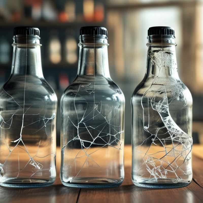
China Top 10 Ways to Improve Bottle Impact Resistance?
Impact resistance starts with a clear failure definition. ISO 2248 drop testing provides a controlled way to expose weak points during handling. Test complete, filled packages, not empty samples. ISO 2248 is the method; the chosen height must reflect your distribution profile. Select 1.0, 1.2, and 1.5 meters for different handling risks. Keep orientation, package mass, temperature, and conditioning time consistent. Record every detail. Floor material matters more than many teams expect. Before testing, inspect the threads, neck finish, shoulder, sidewall, and base. After each drop, check leakage, cap movement, cracks, whitening, dents, and seal loss. Photographs and mass measurements make small failures easier to compare.
A strong protocol separates visible damage from functional failure. A dent may look serious, yet the bottle can remain leak-tight. Conversely, a tiny neck crack can cause delayed leakage. Use a clean absorbent surface and a timed observation period. Pressure or inversion checks may add useful evidence when the package design requires them. Do not hide the ugly result. In one early trial, we focused on side impacts and missed cap displacement after a base-first drop. That mistake changed the sequence. Repeat drops on several samples, because one good bottle proves very little. Compare failure height, failure mode, and product loss. Then adjust base geometry, wall distribution, closure fit, or cushioning, and test again. Material savings are valuable, but fragile shoulders remain a serious warning. Some protocols still need refinement.
Practical engineering actions for plastic bottles, with failure modes defined through controlled free-fall testing. Values shown are recommended starting points for product development and should be confirmed for the specific resin, bottle geometry, closure system, fill level, and distribution environment.
| No. | Improvement Method | Primary Failure Mode Addressed | Recommended Design or Process Control | ISO 2248 Drop-Test Setup | Key Measurements | Engineering Acceptance Focus |
|---|---|---|---|---|---|---|
| 1 | Optimize bottle wall-thickness distribution | Sidewall cracking, puncture, and local buckling | Reduce thin spots in the shoulder, heel, and panel-transition areas; use thickness mapping from at least 12 equally spaced locations around the bottle. | 1.0–1.5 m Drop filled bottles in the worst-case orientation identified during screening. |
Minimum wall thickness, thickness variation, crack length, leakage rate | No through-wall crack or leakage after impact; investigate any local thickness below the approved lower limit. |
| 2 | Improve heel and base geometry | Base fracture, stress whitening, and unstable landing | Use smooth radii, balanced feet, and a controlled transition between the base and sidewall; avoid sharp corners and abrupt thickness changes. | 1.0–1.5 m Include bottom-edge and base-corner impacts on a rigid, non-resilient surface. |
Base deformation, bottle tilt, visible crazing, standing stability | Bottle remains upright when required by the package specification and shows no structural leakage. |
| 3 | Strengthen the shoulder and neck transition | Shoulder splitting, neck cracking, and closure separation | Increase transition radii, remove sharp flow marks, and maintain concentric neck and finish dimensions. | 1.0–1.5 m Test shoulder-first, neck-first, and angled impacts. |
Neck ovality, finish deformation, torque retention, leakage | Closure remains engaged; sealing surface is not distorted beyond the package specification. |
| 4 | Control resin moisture and drying conditions | Brittleness, reduced molecular weight, and premature cracking | Follow the resin supplier’s drying temperature, time, and dew-point requirements; record moisture before molding. | 1.0–1.5 m Compare conditioned material with material at the established moisture limit. |
Resin moisture, impact failures, visual brittleness, processing history | Use a documented moisture-control window; reject lots outside the approved process range. |
| 5 | Stabilize molding and stretch-blow-molding conditions | Weak orientation, uneven crystallinity, and weld-line failure | Control preform temperature, mold temperature, stretch ratio, blow pressure, cycle time, and cooling balance. | 1.0–1.5 m Test samples from start-up, steady-state, and end-of-run production conditions. |
Weight, dimensions, haze, thickness profile, impact failure location | All sampled production stages meet the same failure-mode and leakage criteria. |
| 6 | Select a resin grade with suitable toughness | Low-temperature embrittlement and brittle fracture | Compare candidate materials using tensile, environmental-stress-cracking, and low-temperature impact data; do not select by melt flow alone. | 1.0–1.5 m Condition samples at the minimum and maximum intended use temperatures before testing. |
Fracture type, impact energy response, elongation, leakage | Failure should remain ductile or non-leaking under the defined service-temperature range. |
| 7 | Reduce molding defects and contamination | Crack initiation at black specks, gels, bubbles, scratches, and weld lines | Improve filtration, hopper cleanliness, venting, melt residence-time control, and inspection of regrind content. | 1.0–1.5 m Record the exact impact location and correlate failures with visible defects. |
Defect count, defect size, crack origin, contamination type | No critical defect may intersect a high-stress region or serve as the origin of a through-wall crack. |
| 8 | Verify closure, thread, and seal compatibility | Cap pop-off, thread stripping, seal leakage, and neck damage | Match thread dimensions, closure material, liner or sealing element, application torque, and tamper-evident features. | 1.0–1.5 m Test capped bottles after filling and torque application; include cap-edge impacts. |
Application torque, removal torque, pressure decay, visual leakage | No cap disengagement or product leakage; torque remains within the approved range. |
| 9 | Use realistic fill level and conditioning | Impact variability caused by liquid movement, headspace, or temperature | Define nominal fill, minimum fill, maximum fill, headspace, storage time, and conditioning temperature before comparison testing. | 1.0–1.5 m Test minimum, nominal, and maximum fill conditions with a documented dwell time. |
Fill mass, headspace, internal pressure, failure orientation | The defined worst-case fill condition must meet the same structural and leakage requirements. |
| 10 | Add packaging and distribution validation | Damage from carton compression, pallet movement, abrasion, and repeated handling | Use dividers, protective sleeves, suitable pallet patterns, and adequate restraint; inspect bottles after simulated distribution exposure. | 1.0–1.5 m Drop bottles before and after packaging or distribution simulation to separate product and system failures. |
Scuffing, deformation, leakage, cap displacement, secondary impact damage | Packaging must prevent unacceptable bottle damage throughout the defined handling sequence. |
Test note: ISO 2248 describes a vertical impact test method for complete, filled transport packages. The 1.0–1.5 m heights in this table are development targets, not universal pass/fail requirements. Define the drop sequence, orientation, conditioning, sample quantity, surface, inspection time, and acceptance criteria in the approved test protocol.
: A stable preform creates balanced wall orientation during stretching. Excessive axial stretching can produce thin, weak shoulder zones. Insufficient stretching may leave the wall poorly oriented. Both conditions can cause transport cracking.
Match the stretch ratio with the bottle design and material grade. Check wall thickness near the shoulder, base, and corners. A thicker bottle is not always stronger. Balance matters more.
Low melt temperature may cause incomplete filling and uneven molecular orientation. These defects can create weak areas before stretching begins. Inspect actual melt readings, not only machine settings.
Yes. Excessive heat can reduce polymer viscosity and weaken processing consistency. It may also increase unwanted byproduct formation. Check barrel zones, nozzle temperature, and actual melt temperature. Settings alone are insufficient.
Controlled annealing can reduce internal stress near the gate and base. Too much heat may increase crystallinity and restrict later stretching. Control heating time, temperature, and cooling carefully. The process may still need adjustment.
Polarized-light inspection can show stress patterns inside the preform. These patterns may reveal problems before drop testing. Inspect areas around the gate, shoulder, and base. Some defects are easy to miss.
Sample bottles from different cavities, shifts, and resin lots. Do not choose only visually perfect bottles. Condition every sample at the same temperature and humidity. Small details matter.
Record drop height, bottle orientation, fill level, temperature, cap condition, and failure location. Use realistic bottle volume and handling conditions. Room-temperature results may look acceptable, while chilled bottles fail quickly. This deserves reconsideration.
Instrumented puncture testing measures how rigid plastic absorbs energy before cracking. Compare impact energy, force response, and fracture appearance. Test representative wall sections or molded plaques when appropriate. Average results can hide unstable batches.
Investigate the cavity, shift, material lot, molding temperature, cooling time, and wall thickness. Photograph each failure beside a scale. Repeat testing when the cause is unclear. One pass is not proof. Handling damage may also contribute.
Improving bottle impact resistance requires a structured approach that connects material selection, design, processing, and quality verification. Start by defining likely failure modes through controlled drop testing at 1.0–1.5 meters in accordance with ISO 2248. PET, HDPE, and PP can then be compared using impact data from ISO 180 and ASTM D256 to identify the most suitable material for the intended application. Finite element analysis can help optimize wall thickness, bottle base geometry, and areas prone to stress concentration without adding unnecessary weight.
Production control is equally important. Managing preform stretch ratios, melt temperature, and annealing conditions can reduce internal stress and improve toughness. Finally, production batches should be verified through ASTM D5276 and ISO 6603-2 impact tests to confirm consistent performance. This integrated method helps manufacturers Improve the impact resistance of glass and plastic bottles while supporting reliable quality, efficient material use, and safer handling throughout distribution and everyday use.
